BASIC INFO
Production overviews
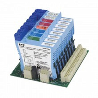
MTL 4500 Intrinsically Safe Isolators MTL4541AS
MTL4541A/AS – MTL5541A/AS CURRENT REPEATER 4/20mA passive i/p for HART® transmitters The MTLx541A provides an input for separately powered 4/20mA transmitters and also allows bi–directional transmission of HART communication signals superimposed on the 4/20mA loop current. Alternatively, the MTLx541AS acts as a current sink for a safe-area connection rather than driving a current into the load.

MTL4541AS safe isolator product specification
SPECIFICATION
See also common specification
Number of channels
One
Location of transmitter
Zone 0, IIC, T4–6 hazardous area if suitably certified
Div.1, Group A, hazardous location
Hazardous area input
Signal range: 4 to 20mA
Under/over-range: 1.0 to 21.5mA
Input impedance for HART signals
at terminals 1, 2: > 230Ω
Maximum input volt drop
at terminals 1, 2: < 6.6V
i.e. a transmitter load of 330Ω at 20mA
Safe-area output
Signal range: 4 to 20mA
Under/over-range: 1.0 to 21.5mA
Safe-area load resistance (MTLx541A)
Conventional transmitters: 0 to 360Ω
Smart transmitters: 250Ω ±10%
Safe-area load (MTLx541AS)
Current sink: 600Ω max.
Maximum voltage source: 24V DC
Safe-area circuit output resistance: > 1MΩ
Safe–area circuit ripple
< 50µA peak-to-peak up to 80kHz
Transfer accuracy at 20°C
Better than 20µA
Temperature drift
< 1µA/°C
Response time
Settles within 200µA of final value after 20ms
Communications supported
HART
LED indicator
Green: power indication
Power requirement (with 20mA signal)
50mA at 20V
45mA at 24V
35mA at 35V
Power dissipation within unit (with 20mA signals)
MTLx541A 0.8W @ 24V dc
MTLx541AS 1.1W @ 24V dc
Safety description
Terminals 1 to 2:
Um = 253V rms or dc.
8.6V (diode). This voltage must be considered when calculating
the load capacitance.
Non-energy-storing apparatus ≤1.5V, ≤0.1A and ≤25mW; can be
connected without further certification into any IS loop with an opencircuit
voltage <28V
MTL4541A/AS – MTL5541A/AS CURRENT REPEATER 4/20mA passive i/p for HART® transmitters The MTLx541A provides an input for separately powered 4/20mA transmitters and also allows bi–directional transmission of HART communication signals superimposed on the 4/20mA loop current. Alternatively, the MTLx541AS acts as a current sink for a safe-area connection rather than driving a current into the load.

MTL4541AS safe isolator product specification
SPECIFICATION
See also common specification
Number of channels
One
Location of transmitter
Zone 0, IIC, T4–6 hazardous area if suitably certified
Div.1, Group A, hazardous location
Hazardous area input
Signal range: 4 to 20mA
Under/over-range: 1.0 to 21.5mA
Input impedance for HART signals
at terminals 1, 2: > 230Ω
Maximum input volt drop
at terminals 1, 2: < 6.6V
i.e. a transmitter load of 330Ω at 20mA
Safe-area output
Signal range: 4 to 20mA
Under/over-range: 1.0 to 21.5mA
Safe-area load resistance (MTLx541A)
Conventional transmitters: 0 to 360Ω
Smart transmitters: 250Ω ±10%
Safe-area load (MTLx541AS)
Current sink: 600Ω max.
Maximum voltage source: 24V DC
Safe-area circuit output resistance: > 1MΩ
Safe–area circuit ripple
< 50µA peak-to-peak up to 80kHz
Transfer accuracy at 20°C
Better than 20µA
Temperature drift
< 1µA/°C
Response time
Settles within 200µA of final value after 20ms
Communications supported
HART
LED indicator
Green: power indication
Power requirement (with 20mA signal)
50mA at 20V
45mA at 24V
35mA at 35V
Power dissipation within unit (with 20mA signals)
MTLx541A 0.8W @ 24V dc
MTLx541AS 1.1W @ 24V dc
Safety description
Terminals 1 to 2:
Um = 253V rms or dc.
8.6V (diode). This voltage must be considered when calculating
the load capacitance.
Non-energy-storing apparatus ≤1.5V, ≤0.1A and ≤25mW; can be
connected without further certification into any IS loop with an opencircuit
voltage <28V


