


Rosemount 2051L2AA0FC21ABM5D4V5C1CTQ4Q8F8 Liquid Level Transmitter for Process Vessels
Rosemount 2051L Level Transmitter for Direct-Mounted Tank Measurement
Rosemount 2051L2AA0FC21ABM5D4V5C1CTQ4Q8F8 is a configured 2051L liquid-level transmitter. The 2051L platform combines a differential-pressure transmitter with a direct-mount process flange and diaphragm-seal arrangement for hydrostatic level measurement. It is used on vented or pressurized vessels where the engineering team wants a compact assembly, defined wetted materials, and a transmitter configuration matched to the tank and process.
Level accuracy depends on more than the transmitter specification. Vessel pressure, liquid density, process temperature, fill fluid, flange elevation, reference-leg condition, capillary arrangement, and ambient temperature can all influence the result. The complete order code therefore needs to be checked against the tank datasheet and the latest Emerson configuration records.
Turning tank data into a valid measurement range
For an open tank, hydrostatic head is determined mainly by liquid density and the vertical distance between the lower measuring point and the desired level. A closed tank also requires the vapor-space pressure to be applied to the low-pressure side or compensated through an appropriate seal arrangement. Zero elevation or suppression may be required depending on transmitter location and seal geometry.
The engineering calculation should use minimum and maximum process density, not only a nominal value. Temperature changes, composition variation, or interface formation can shift density and therefore the indicated level. Record the lower-range value, upper-range value, units, normal operating level, alarm points, and any wet-leg or dry-leg assumptions before configuration.
| Selection record | Information needed |
|---|---|
| Model | 2051L2AA0FC21ABM5D4V5C1CTQ4Q8F8 |
| Vessel | Open or pressurized, nozzle location, flange standard and rating |
| Process | Liquid, density range, temperature, pressure and compatibility |
| Measurement | Level span, elevation/suppression, response time and accuracy objective |
| Electrical | Protocol, display, power, entries, approvals and alarm behavior |
Mechanical and environmental checks
Confirm that the flange face, gasket, bolt material, and pressure rating match the vessel nozzle. The diaphragm must not be damaged during handling or cleaning. Fill-fluid and wetted-material compatibility should be reviewed for corrosion, vacuum service, high temperature, hygienic requirements, and process permeation. If the assembly uses a remote seal or capillary, routing and support should minimize temperature imbalance and physical damage.
The transmitter housing should remain accessible for wiring, local indication, and maintenance. Cable glands and grounding must maintain the specified protection. After installation, perform a leak check, verify the correct high- and low-side relationships, confirm zero under the known reference condition, and test the output at the control system. Safety-related applications require the approved safety manual and proof-test procedure for the exact configuration.
Commissioning and troubleshooting level accuracy
Before applying pressure, inspect the diaphragm surface and confirm that protective covers used for shipping have been removed only as directed. Never press on or mechanically clean a diaphragm with a hard tool. Confirm transmitter orientation, process connection, venting or draining provisions, and the intended reference condition. Configure the correct engineering units and range, then compare the indicated level with a known vessel condition or an independent reference. Record ambient and process temperatures during this check.
If the reading has a constant offset, review mounting elevation, zero suppression or elevation, reference-leg head, and transmitter zero. If the error changes with temperature, examine fill-fluid selection, capillary symmetry, sun exposure, and ambient gradients. A slow response can result from long capillaries, cold fill fluid, blocked impulse paths, or process buildup. A noisy signal may originate from agitation, flashing, density variation, poor damping selection, grounding, or an unstable vapor space. Diagnose the whole installation before trimming the transmitter to fit one process condition.
Details that improve procurement accuracy
Include the full model code, quantity, tank drawing, nozzle size and rating, measured liquid, density and temperature ranges, design pressure, required level span, transmitter mounting elevation, hazardous-area classification, output protocol, display, material certificates, calibration points, and documentation language. If replacing an existing assembly, provide overall dimensions and clear photographs of the transmitter, process flange, seal, and nameplate.
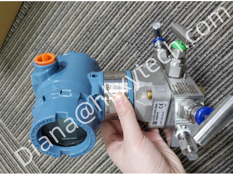
The photograph on this page shows a Rosemount pressure transmitter with a manifold and is a series reference, not a photograph of the exact 2051L flange assembly. Do not use the image alone for mechanical selection. Verify the delivered model, seal construction, flange, materials, fill fluid, and option codes against Emerson’s current product data sheet and the order acknowledgement.
