


Eaton Crouse-Hinds MTL7729P+ High-Power Zener Barrier for IIB Solenoid Valve and Alarm Circuits
Engineering an MTL7729P+ Intrinsically Safe Output Loop
The Eaton Crouse-Hinds series MTL7729P+ is not selected simply because a solenoid valve needs “an MTL barrier.” It is a positive-polarity, high-power zener barrier intended for suitable IIB digital-output circuits. Its job is to limit fault energy entering hazardous-area wiring while still allowing enough normal operating power to reach an alarm, LED, solenoid valve, or similar on/off load.
A successful design must satisfy two different questions. First, will the load operate at the end of the real cable with the minimum supply voltage? Second, do the barrier, field device, cable, earth system, and hazardous-area classification form an approved intrinsically safe circuit? Passing only one of these checks is not enough.
Start with the field load, not the barrier catalogue
Collect the load’s pickup voltage, holding voltage, operating current, polarity, and duty cycle. Solenoid coils often demand more current during pickup than they need to remain energized. Long cables and cold-weather operation can change the available voltage. Use worst-case values rather than the most convenient nominal figures.
Eaton’s MTL7700 application guidance identifies the MTL7729P+ as a high-power option for applicable IIB digital outputs. The published safety description includes 28 V, 164 Ω, and 170 mA. These values help define the certified energy limitation; they are not a promise that every IIB solenoid will operate. The load line and loop voltage still need to be calculated.
Build a conservative voltage budget
Available field voltage equals the minimum supply voltage minus controller or output losses, barrier drop, and cable drop.
Compare the resulting field voltage with the load requirement at the necessary current. Include conductor resistance for the complete outgoing and return path. If the design has little margin, test at the lowest supply tolerance and highest expected cable resistance. Do not solve a marginal circuit by changing to another barrier until the intrinsic-safety assessment has also been repeated.
Prove the intrinsic-safety relationship
The barrier output parameters must be compatible with the field device input parameters, and the permitted cable capacitance and inductance must cover the installed cable. Gas group is especially important: MTL7729P+ is presented as the higher-power choice for suitable IIB applications, while IIC applications can require a different solution such as the lower-power MTL7728P+ arrangement. Electrical operation alone does not demonstrate certification compliance.
The engineering file should identify the current barrier certificate, field-device certificate, entity-parameter comparison, cable type and length, hazardous-area zone or division, gas group, temperature class, and ambient-temperature limits. If a drawing uses a legacy MTL729P+, Eaton’s cross-reference information points to MTL7729P+ as the nearest MTL7700-range counterpart, but the replacement must still be checked against the original loop design and current standards.
Treat the intrinsic-safety earth as a safety component
Zener barriers depend on a high-integrity earth path. The MTL7700 module clamps to a standard T-section DIN rail, and the rail installation forms part of the earthing arrangement. Rail bonding, conductor size, termination method, enclosure earth, and inspection access must comply with the site standard and applicable code. Paint, corrosion, loose rail hardware, or an undocumented cabinet modification can undermine the protection concept.
Maintain segregation between intrinsically safe and non-intrinsically safe wiring. Removable terminals make maintenance easier, but they also make clear labeling essential. A technician should be able to identify the safe-area supply, controller output, hazardous-area conductors, and earth connection without relying on wire color alone.
Commission the complete loop under realistic conditions
A useful commissioning sequence is:
- Verify the exact MTL7729P+ model and certificate marking before installation.
- Check DIN-rail attachment, earth continuity, terminal numbering, and polarity with power isolated.
- Measure the safe-area supply at minimum and normal operating conditions.
- Energize the output and confirm field voltage, loop current, load pickup, and load release.
- Operate the controller command repeatedly and confirm the intended safe state after power loss or an open circuit.
- Record measured values, cable details, certificate references, and the final loop drawing.
A repeated trip or failure to pick up should not be treated automatically as a defective barrier. Check for reversed polarity, excessive cable resistance, an unsuitable coil, poor earthing, incorrect supply voltage, damaged wiring, or use of the wrong 7700-series model. Replacing the unit by appearance can introduce a barrier with a different resistance or safety description.
What the supplied photograph does—and does not—show
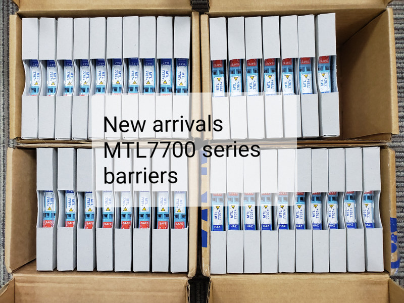
The image supplied for this news item shows boxed MTL7700-series inventory. Several visible module labels are other 7700-range models, not a clearly readable MTL7729P+ nameplate. The photograph is therefore useful as a series and stock reference, but it cannot confirm the requested electrical function. Receiving inspection must verify the MTL7729P+ marking, terminal arrangement, approval label, package identification, and Eaton documentation before the barrier is accepted for an intrinsically safe loop.
