


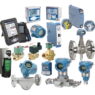
Rosemount 3051CD1A02A1AH2B1E5L4M5Q4Q8DF Differential Pressure Transmitter: Configuration, Loop Fit and Installation Review
Rosemount 3051CD1A02A1AH2B1E5L4M5Q4Q8DF is the complete model code requested for this product entry. The 3051 family supports pressure measurement, and the 3051C/Copanar configuration family is used in differential-pressure applications. Because each code segment identifies a configuration choice, preserve the complete code in purchasing and replacement documents.
Differential-pressure transmitters are commonly applied in flow, level and pressure measurement arrangements when paired with the appropriate primary element, impulse piping or process connection. The transmitter's calibrated span and installation orientation must suit the measurement task. Range selection, zero elevation or suppression, damping and engineering units should be checked against the instrument configuration and the approved control-loop documentation.
| Complete model code | Rosemount 3051CD1A02A1AH2B1E5L4M5Q4Q8DF |
| Product family | Rosemount 3051CD |
| Measurement application | Differential pressure; confirm the installed range and calibrated span |
| Output and protocol | Verify against the nameplate and current configuration record |
| Process connection and materials | Confirm the exact manifold, wetted materials and installation options |
| Display and approvals | Confirm included options and certification markings on the delivered instrument |
This specific order code should be checked as one complete string. Pressure range, process connection, output, display, materials, manifold/seal assembly and approvals must not be inferred from the 3051 prefix alone. A replacement may require a different configuration if the installed process conditions or project specification have changed.
Before commissioning, inspect the process connection and manifold arrangement for compatibility with the line pressure, process fluid and temperature. Ensure impulse lines or capillaries, where used, are routed and equalized correctly for the measurement. Follow the plant isolation, venting and pressure-testing procedure; an incorrect valve sequence or trapped pressure can create unsafe readings or damage the sensing system.
For troubleshooting, compare the local indication and control-system value with a known reference, and check loop power, wiring, grounding and configured range. A zero shift, unstable reading or slow response may arise from plugged or leaking impulse lines, incorrect manifold operation, temperature effects, mounting stress or configuration—not necessarily a failed transmitter. Record as-found values before making adjustments.
Before requesting a quotation
- Photograph the complete nameplate and retain every code character.
- State the measured variable, calibrated range, units and operating pressure.
- Identify process connection, manifold, seal and wetted-material requirements.
- Confirm output protocol, display, electrical entry and area approvals.
- Provide quantity, destination and delivery requirements.
For installation or replacement, compare the delivered configuration with the loop documentation and current instrument setup. Do not substitute a different 3051 variant by matching only the housing or product-family name.
