

Yokogawa FLXA21 Contacting Conductivity Analyzer for Industrial Water Systems
The Yokogawa FLXA21-D-U-D-AA-C1-NN-A-N-LA-N-N/USCTT is a configured two-wire liquid analyzer for contacting conductivity and resistivity measurement. The C1 input code identifies a contacting-conductivity channel, while the listed configuration has no second measurement input. This type of analyzer is used with a compatible two-electrode or four-electrode conductivity sensor to monitor ionic concentration, water purity, chemical strength, rinsing quality, and process changes.
FLXA21 is a modular, loop-powered analyzer platform with a local touch interface and diagnostic functions. Yokogawa publishes nominal 24 VDC two-wire power and an isolated 4–20 mA output with HART communication for the A output code. Depending on sensor cell constant and configured range, the contacting-conductivity input covers applications from high-purity water to concentrated process solutions. The exact housing, coating, special treatment, approvals, and /USCTT option must be checked against the order record.
Measurement Uses
Contacting conductivity is widely used in demineralized water, boiler feedwater, condensate return, reverse-osmosis systems, cooling water, clean-in-place processes, chemical blending, rinse tanks, and wastewater treatment. A low cell constant can suit high-purity water, while a higher cell constant can extend measurement into more conductive solutions. Selection must consider expected range, temperature, chemical compatibility, flow, pressure, and the tendency for coating or polarization.
Resistivity is the inverse representation of conductivity and is common in high-purity water systems. Temperature compensation is essential because conductivity can change significantly with temperature even when solution concentration remains constant. The analyzer must use the correct temperature element and compensation method for the sensor and process. Applying the wrong reference temperature or compensation curve can create a stable but misleading result.
Key Product Data
| Verification point | Information for this product page |
|---|---|
| Requested configuration | FLXA21-D-U-D-AA-C1-NN-A-N-LA-N-N/USCTT |
| Measurement input | C1 contacting conductivity; no second input listed |
| Compatible sensor principle | Two-electrode or four-electrode conductivity sensor |
| Published display range | 0.01 µS/cm to 2000 mS/cm, dependent on cell constant and configuration |
| Published resistivity range | 0.001 kΩ·cm to 1000 MΩ·cm |
| Signal | 4–20 mA with HART for applicable A-code configuration |
| Protection | FLXA21 family IP66/NEMA 4X-class enclosure, subject to configuration |
Sensor and Range Selection
Confirm the sensor cell constant, electrode material, temperature element, process connection, cable length, and expected conductivity range before configuration. Yokogawa documentation identifies support for cell constants from 0.005 to 50 cm⁻¹ across the FLXA21 contacting-conductivity family. The selected sensor and installation determine the practical range. High-purity measurements also require careful material selection and a flow arrangement that avoids air bubbles and sample contamination.
In aggressive or dirty processes, electrode coating can reduce response and create measurement error. Four-electrode sensors may provide a wider useful range in some conductive solutions, while two-electrode sensors are common for clean and lower-conductivity applications. The buyer should verify that the analyzer input, sensor wiring, and cable type form an approved measurement loop.
Installation and Commissioning
Mount the analyzer in a location suitable for the selected enclosure, leaving room for wiring and service. Seal unused entries and keep sensor wiring away from power cables, motors, and drive outputs. Connect shield and grounding conductors according to the Yokogawa installation manual. Confirm that the loop supply can support the analyzer, receiving resistor, cable voltage drop, and any intrinsic-safety interface.
Commissioning should verify cell constant, temperature sensor type, units, range, output scaling, damping, temperature compensation, alarm behavior, and HART communication. Use a traceable conductivity standard when process calibration is required. For pure-water applications, installation quality and sample handling can have more influence than a conventional solution calibration, so compare the result with a controlled reference and documented operating condition.
Maintenance and Troubleshooting
Review sensor cleanliness, cable condition, temperature reading, and process flow before adjusting calibration. A sudden conductivity change may be a real process event, a trapped bubble, a temperature-compensation issue, contamination, damaged insulation, or an incorrect range. Trend data and analyzer diagnostics can help separate gradual sensor fouling from a fast process change.
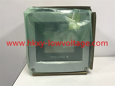
The reused image shows an FLXA-family analyzer, but its protective packaging hides the full nameplate. Verify FLXA21-D-U-D-AA-C1-NN-A-N-LA-N-N/USCTT from the label and project documentation. For quotation, provide the full model, sensor code, cell constant, range, temperature, process connection, communication, approvals, quantity, and destination.
