


Pepperl+Fuchs KFD2-SH-Ex1.T.OP SIL 3 Switch Amplifier
The Pepperl+Fuchs KFD2-SH-Ex1.T.OP is a one-channel isolated barrier and switch amplifier for transferring digital signals from a hazardous area to a safe-area control system. It accepts approved dry contacts or SN/S1N proximity sensors, monitors the field circuit for lead breakage and short circuit, and provides an active voltage output, a relay contact output, and a separate fault indication output.
The device is designed for functional-safety applications up to SIL 3 according to IEC/EN 61508 when the specified output and safety instructions are used. It also supports applications up to Performance Level d under EN ISO 13849. Safety capability applies only when the complete loop, installation, proof testing, and lifecycle management follow the manufacturer’s safety documentation and the plant's approved design.
Signal Transfer and Fault Response
The field input is connected on the hazardous-area side, while the outputs interface with the safe-area logic. The input controls the active voltage output and the relay contact. Pepperl+Fuchs specifies continuous monitoring for lead breakage and short circuit. During a detected fault, the fault output and the controlled outputs de-energize according to the documented function. A mechanical contact requires the prescribed resistor network so the module can distinguish normal switching from wiring faults.
The active voltage output responds faster than the relay and is the output designated for SIL 3 applications in the manufacturer documentation. The relay output can support suitable SIL 2 arrangements. The engineer must verify the required safe state, response time, proof-test interval, load, and control-system input. Do not combine outputs or change resistor values without checking the approved safety circuit.
Key Product Data
| Verification point | Information for this product page |
|---|---|
| Model / document number | KFD2-SH-Ex1.T.OP / 70100833 |
| Channels and input | One channel; approved dry contact or SN/S1N sensor |
| Supply | 20–30 VDC through Power Rail or terminals 14+ and 15− |
| Outputs | Active voltage output, relay NO contact, and relay fault output |
| Diagnostics | Lead-breakage and short-circuit monitoring |
| Functional safety | Up to SIL 3; systematic capability SC 3; up to PL d |
| Mechanical | 20 × 119 × 115 mm; IP20; 35 mm DIN-rail mounting |
| Ambient temperature | −20 to +60 °C |
Field Device and Wiring Selection
Confirm that the field device is an approved SN/S1N proximity sensor or a suitable dry contact with the required series and parallel resistors. Check hazardous-area entity parameters, cable capacitance and inductance, line resistance, grounding, and separation from non-intrinsically-safe wiring. The barrier documentation lists dedicated terminal assignments for the input, active output, relay output, fault relay, and supply.
Use a regulated 24 VDC supply or compatible Power Rail installation. Review total cabinet power, heat dissipation, fuse protection, collective error messaging, and module spacing. The IP20 housing requires installation inside a suitable enclosure. Mark the front label with the loop identity so maintenance staff can relate field wiring, PLC logic, and safety documentation.
Commissioning and Functional-Safety Checks
Commissioning should test normal ON and OFF states, sensor current thresholds, active output, relay contact, fault output, lead-break simulation, and short-circuit simulation. Confirm that the control system displays the correct process and diagnostic states. Measure response only with approved procedures and avoid defeating the safety function during live operation.
For a safety instrumented function, retain the safety manual, calculation assumptions, proof-test procedure, test results, and device identification. Replacement with a visually similar switch amplifier is not sufficient. The model, revision, safety parameters, input sensor type, resistor network, output used, and installed configuration must match the validated design.
Photo and Model Verification
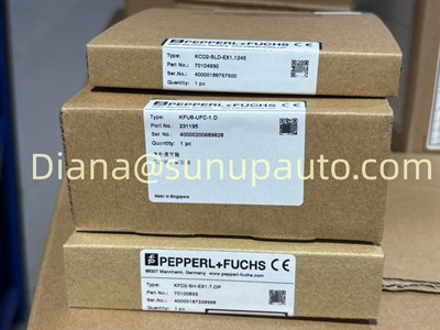
The reused photograph shows a Pepperl+Fuchs KFU8-UFC-1.D frequency converter rather than a KFD2-SH-Ex1.T.OP switch amplifier. It is retained only because the spreadsheet assigns that existing image to this model. These products have different functions and must not be treated as interchangeable. Final supply must be verified by the KFD2-SH-Ex1.T.OP label, part/document number, terminals, certificates, and current manufacturer data.
For quotation, provide the full model, quantity, field sensor or contact type, hazardous-area classification, required SIL or PL, control-system input, Power Rail use, certificates, and destination. This information helps confirm both ordinary signal compatibility and functional-safety requirements.
