

Yokogawa VJQ8-027-2AA0/SN Pulse-to-Analog Converter
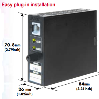
The Yokogawa VJQ8-027-2AA0/SN is a configured JUXTA VJ-series pulse-to-analog converter for converting frequency or pulse signals into standard analog signals used by PLC, DCS, recorder, indicator, and control systems. It is well suited to speed, flow, totalizer, rotating-equipment, and production-rate applications where a pulse source must be isolated, scaled, and transmitted as a stable analog value.
The VJQ8 is a multifunction converter that supports field configuration with the Yokogawa VJ77 parameter-setting tool. Published family information lists isolated single- and dual-output arrangements, selectable voltage or current outputs, alarm or RS-485 options on relevant configurations, and AC/DC or low-voltage DC power choices. The exact meaning of every character in VJQ8-027-2AA0/SN should be checked against the current Yokogawa ordering guide.
Process Measurement Advantages
- Converts pulse or frequency information into a proportional analog process signal.
- Supports integration of flowmeters, speed pickups, counters, and other pulse-producing devices.
- Provides electrical isolation between field input and receiving control equipment.
- Configurable conversion range, low-cut behavior, filtering, and sampling functions.
- Compact plug-in JUXTA format for organized panel installation and maintenance.
- Useful for retrofit projects that require a conditioned signal without replacing the field sensor.
Engineering Information Required
Successful configuration starts with the input source. Specify pulse type, amplitude, frequency range, minimum and maximum process values, sensor power requirement, contact or open-collector characteristics, low-cut point, input filter, sampling method, and response-time requirement. Then confirm the required output range, number of isolated outputs, receiving load, power supply, alarm or communication function, and installation base.
Allow the device to reach its specified warm-up condition before precision verification. Commissioning should include zero and span checks at several input frequencies, output-load confirmation, isolation and grounding review, and verification of the configured parameters. Noise-generating power and signal cables should be routed separately from the low-level pulse input according to the installation manual.
Typical Measurement and Control Applications
In flow measurement, the converter can translate the pulse frequency from a turbine, positive-displacement, magnetic, or other pulse-output flowmeter into an analog signal representing instantaneous flow. In rotating machinery, pulses from a proximity switch, magnetic pickup, or encoder can be scaled to motor speed, conveyor speed, fan rotation, or production rate. The analog output can then be used by a controller, recorder, indicator, or legacy monitoring system that does not accept the original pulse signal directly.
The engineering calculation should clearly relate input frequency to process units. Document the frequency at zero and full scale, the desired output at each point, damping or averaging, low-frequency cutoff, and the required response to loss of input. For applications with rapidly changing speed, excessive filtering may hide a real process change; for unstable pulses, too little filtering may create a noisy output. The correct balance should be confirmed during loop testing with representative operating conditions.
Replacement, Calibration, and Documentation
A replacement converter should be compared with the original device at both the hardware and parameter levels. Verify the terminal base, supply voltage, input circuit, output type, isolation arrangement, and any communication or alarm option. Capture the existing parameter set before removing a working unit whenever possible. If no configuration record is available, measure the field signal and review the control-system scaling before programming the replacement.
Acceptance testing should apply several known input frequencies across the operating range and record the corresponding analog outputs. Check zero, mid-scale, full scale, alarm behavior, and response after power cycling. Label the installed device with its loop number and retain a configuration report for maintenance. These steps reduce the risk of a converter that is electrically functional but incorrectly scaled for the process, which can lead to inaccurate indication, control error, or false production totals.
Photo and Suffix Verification
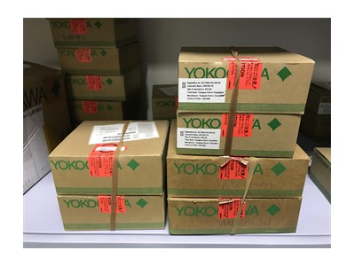
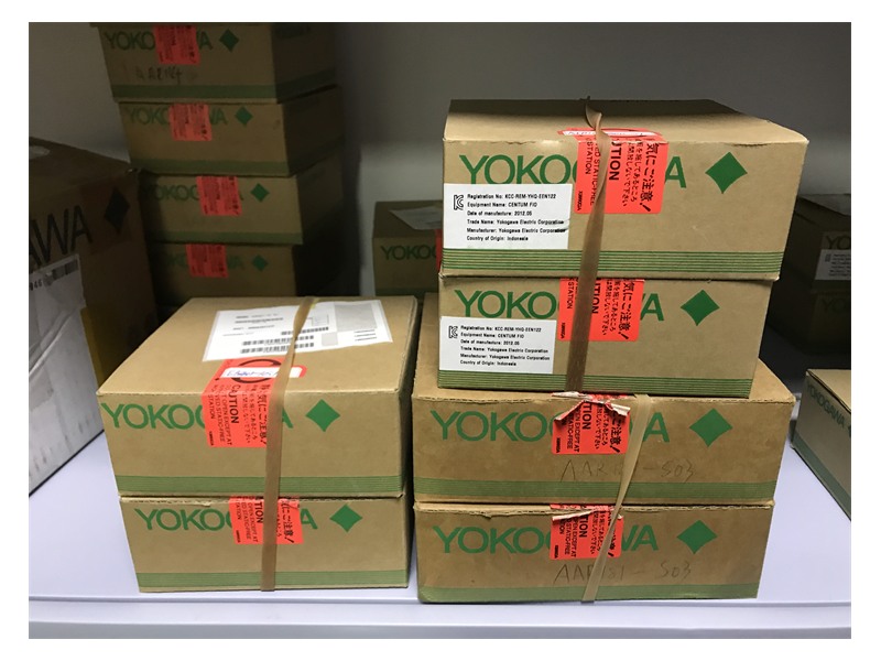
The supplied photograph shows sealed Yokogawa cartons, but the visible labels do not clearly confirm VJQ8-027-2AA0/SN. It is used as a brand and inventory reference rather than proof of the exact configured model. Confirm the full suffix, carton label, product nameplate, output count, power code, transmitter supply, output ranges, and option code before shipment.
For price and availability, provide the complete order code, input pulse specifications, desired analog outputs, power supply, installation base, parameter settings, required certificates, quantity, and delivery destination. For replacement service, a photo of the existing terminal label and a copy of the current configuration reduce commissioning risk.