


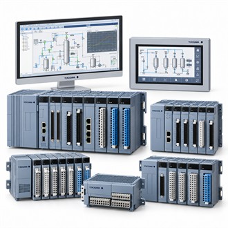
Pulse measurement integration with the Yokogawa AAP135-S50
Yokogawa AAP135-S50 is counting or measuring pulse signals delivered from compatible field devices into a CENTUM system. For AAP135-S50, establish the installed system and intended duty before treating a family-level match as a replacement decision. The exact AAP135-S50 string should remain tied to the equipment tag, I/O schedule and current drawings.
Configuration boundaries
The selected build describes the manufacturer's specified contact, voltage and current pulse input modes, isolated channels and applicable frequency limits. When specifying AAP135-S50, separate verified characteristics from assumptions about options not shown in the ordered suffix. This avoids confusing a module or instrument family with a complete system package. Record the full AAP135-S50 code wherever the associated configuration is reviewed.
Specification snapshot
| Selection point | Specification / confirmation |
|---|---|
| Representative model | AAP135-S50 |
| Module role | Pulse input module |
| Input types | Contact, voltage or current pulse modes are specified for the family |
| Channel count | Eight isolated input channels per manufacturer specification |
| Check | Confirm pulse levels, frequency, terminal board and system compatibility |
Application fit
Review pulse amplitude, pulse width, source type, maximum rate, counter or frequency use, cable run and the required host-side calculation. The correct fit for AAP135-S50 depends on the complete process or control context, not on the model prefix alone. Compare applicable electrical, environmental, process and interface constraints with the manufacturer's documentation before installation.
Replacement and commissioning
Before release, check the signal mode, electrical thresholds, channel isolation, terminal board, cable and system configuration for this exact module style. For AAP135-S50, plan installation and verification around the real field wiring and host configuration. test with representative pulse sources and compare count or frequency results with the device and configured control-system point. Keep the as-found configuration and final test record with the instrument or system tag.
Model-code verification
For Yokogawa AAP135-S50, include the complete nameplate code, application, interface and operating conditions in the enquiry. Retain AAP135-S50 with the equipment record and verify the applicable specification before replacement or project release.
