


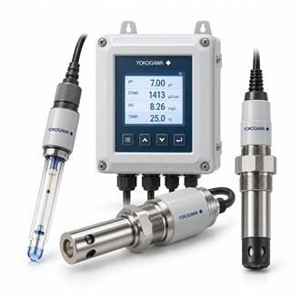
Two-channel measurement and sensor matching: Yokogawa DC402G-1-2-E/PM/U
The complete code DC402G-1-2-E/PM/U is the starting point for selecting Yokogawa DC402G-1-2-E/PM/U. Identify the application, connected equipment and supply boundary before comparing alternatives. The specifications below provide a concise view of DC402G-1-2-E/PM/U; verify every interface against the exact installation.
| Selection point | Specification / confirmation |
|---|---|
| Representative model | DC402G-1-2-E/PM/U |
| Product | Dual-channel conductivity converter |
| Measurement chain | Compatible sensor on each channel |
| Configuration | Confirm display, output and power |
| Verification | Channel setup and scaling |
Define what the device must do
DC402G-1-2-E/PM/U is listed as a dual-channel conductivity converter. The complete measurement depends on the connected conductivity sensors, channel setup and sample conditions. For Yokogawa DC402G-1-2-E/PM/U, define whether both channels serve separate measurements or a related process arrangement and identify the sensors before setting the input configuration. The complete Yokogawa DC402G-1-2-E/PM/U identity should remain visible in the equipment file and purchase enquiry so the offered configuration can be reconciled with the approved application.
Check the complete installation
Commissioning of DC402G-1-2-E/PM/U should check each channel independently, including sensor recognition, temperature behavior, displayed units and output scaling. Preserve the setup and verification records for both channels. When requesting Yokogawa DC402G-1-2-E/PM/U, state the measurement ranges and whether a complete sensor package is required. The complete Yokogawa DC402G-1-2-E/PM/U identity should remain visible in the equipment file and purchase enquiry so the offered configuration can be reconciled with the approved application.
Selection points
- Channel-by-channel sensor and cell data
- Temperature element and compensation
- Mounting, outputs and supply requirements
- Independent verification of both channels
Record the as-left configuration
Verify the DC402G-1-2-E/PM/U code, panel or field mounting, sensor inputs, outputs and power requirements against the product specification. Confirm the cell constants, temperature elements and analyzer configuration for each channel. Distinguish the converter from the sensors, fittings and cabling in the purchase scope for Yokogawa DC402G-1-2-E/PM/U. The complete Yokogawa DC402G-1-2-E/PM/U identity should remain visible in the equipment file and purchase enquiry so the offered configuration can be reconciled with the approved application.
Procurement details
For a quotation on DC402G-1-2-E/PM/U, provide the quantity, required delivery date, equipment tag, full suffix and whether the request is for a new installation or replacement. Identify the associated sensor, converter, cable, terminal unit or other interfaces where relevant. State the documents, calibration records and accessories expected with delivery. Before releasing Yokogawa DC402G-1-2-E/PM/U for installation, check the supplied nameplate and package contents against the agreed scope.
Equipment record
At receipt, match Yokogawa DC402G-1-2-E/PM/U to the enquiry, approved drawings and installation location. Keep the product code, system revision, related equipment and acceptance checks together. If the delivered DC402G-1-2-E/PM/U differs from the specified configuration, pause installation and have the deviation reviewed by the responsible engineer. This simple handover keeps spare identification and future maintenance for Yokogawa DC402G-1-2-E/PM/U tied to the equipment that was actually supplied.
