


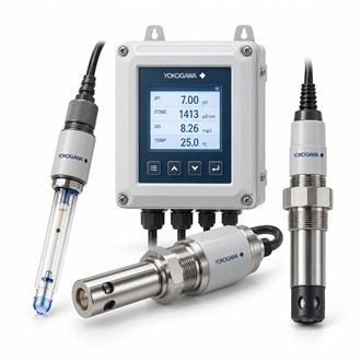
Configuring liquid measurement with the Yokogawa FLXA402-A-B-AB-P1-NN-A2-WR-N-N-N-NN-UM
Yokogawa FLXA402-A-B-AB-P1-NN-A2-WR-N-N-N-NN-UM provides multi-parameter online liquid analysis using compatible measurement and sensor modules. The first decision is whether that role matches the installed architecture. For FLXA402-A-B-AB-P1-NN-A2-WR-N-N-N-NN-UM, identify the associated equipment, control or measurement point, and the expected behavior during startup, normal operation and fault conditions.
Specification snapshot
| Selection point | Specification / confirmation |
|---|---|
| Representative model | FLXA402-A-B-AB-P1-NN-A2-WR-N-N-N-NN-UM |
| Analyzer family | FLXA402 4-wire modular liquid analyzer |
| Measurement options | pH/ORP, contacting or inductive conductivity, DO and other modules by build |
| Sensor capacity | Up to five sensors supported by the platform, subject to configuration |
| Verify | Check exact module code, supply, outputs, enclosure and sensor compatibility |
Technical review
For FLXA402-A-B-AB-P1-NN-A2-WR-N-N-N-NN-UM, focus on the analyzer's four-wire platform, measurement modules, sensor arrangement, user interface and configured output/communication options. Review the manufacturer's limits alongside project requirements; the model-family description alone is not a guarantee that every option is present in this build. Preserve the complete FLXA402-A-B-AB-P1-NN-A2-WR-N-N-N-NN-UM identifier in quotations and technical submittals to avoid ambiguity.
Engineering inputs
The application review should define the selected analytical parameter, sensor technology, process conditions, cable distance, maintenance access and host control-system interface. These details help determine the proper range, signal interface, mounting method and supporting accessories for FLXA402-A-B-AB-P1-NN-A2-WR-N-N-N-NN-UM. Where legacy equipment is involved, also check service availability and an approved migration path before promising interchangeability.
Acceptance checks
Use the checks in the table and verify each configuration segment, sensor-module pairing, power and area rating, analog/digital outputs, relay needs and communication protocol. After installation of FLXA402-A-B-AB-P1-NN-A2-WR-N-N-N-NN-UM, test the actual field signal or control response, inspect alarms and communication status, and save the resulting parameters. sensor health, calibration status and measurement configuration should be reviewed together when commissioning or adding a second measurement.
Related model configurations
The following codes are related configurations for comparison. They are not asserted as direct equivalents.
- FLXA402-A-B-AD-P1-NN-A2-WR-N-N-N-EX/UM
- FLXA402-A-B-AG-C1-NN-A2-WR-N-N-N-NN/UM
- FLXA402-A-B-AJ-P1-A4-NR-N-N-N-NN/UM/SCT/CD4
- FLXA402-A-D-AD-P1-NN-A2-NR-N-N-N-NN/UM/H6/SCT
- FLXA402-D-B-AB-P1-NN-A2-NR-N-N-N-NN/U
Model-code verification
For Yokogawa FLXA402-A-B-AB-P1-NN-A2-WR-N-N-N-NN-UM, include the complete nameplate code, application, interface and operating conditions in the enquiry. Retain FLXA402-A-B-AB-P1-NN-A2-WR-N-N-N-NN-UM with the equipment record and verify the applicable specification before replacement or project release.
