


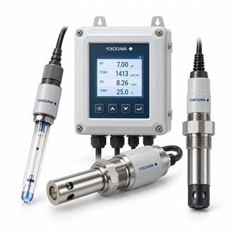
Sensor installation and liquid compatibility: Yokogawa ISC40G-GG-T1-10
For a new project or an installed-equipment replacement, Yokogawa ISC40G-GG-T1-10 should be evaluated against the actual application. It is an inductive conductivity sensor. The specification table below provides an early overview; the following sections explain the practical questions to resolve when selecting ISC40G-GG-T1-10.
Selection data
| Selection point | Specification / confirmation |
|---|---|
| Representative model | ISC40G-GG-T1-10 |
| Principle | Inductive conductivity measurement |
| Type | General-purpose ISC40G family |
| Application | Compatible process-liquid conductivity duty |
| Selection | Material, mounting, cable and analyzer |
Match the sensing method to the liquid
ISC40G-GG-T1-10 measures conductivity by the inductive method and is intended for a compatible process-liquid measurement system. Review the conductivity range and liquid chemistry before selecting the sensor. For ISC40G-GG-T1-10, the suitability of wetted materials and the available installation space should be established separately from the electrical compatibility of the connected analyzer.
Allow for the surrounding process geometry
The installation of ISC40G-GG-T1-10 should follow the prescribed clearances and mounting arrangement for the sensor. Nearby surfaces, trapped air and an unrepresentative sample location can undermine a conductivity measurement. For ISC40G-GG-T1-10, retain the fitting details and any installation-factor settings with the loop documentation so a later sensor replacement preserves the intended measurement geometry.
- Liquid composition and conductivity range
- Wetted material and process limits
- Mounting clearances and fitting details
- Analyzer, cable and compensation settings
Temperature and cleaning affect the result
An application review for ISC40G-GG-T1-10 should state the temperature-compensation approach, expected deposits and planned cleaning method. Confirm cable routing, terminations and analyzer configuration during commissioning. After maintenance of ISC40G-GG-T1-10, compare the measurement under known process conditions and retain the results with the equipment tag, rather than changing compensation settings simply to force agreement with an unrelated reading.
Sensor and sample information to provide
State the liquid composition, expected measurement range, temperature and sample location. Identify the analyzer or meter, sensor connection, cable and fitting included in the required supply. For an existing installation, include calibration information and any cleaning or fouling history that affects selection. A complete enquiry should also distinguish a bare sensor from an assembled measuring package and specify the documentation needed at delivery. Preserve the exact ISC40G-GG-T1-10 designation on the enquiry and confirm the offered ISC40G-GG-T1-10 configuration before release.
Purchase and installation record
Keep the technical and purchasing records for ISC40G-GG-T1-10 connected: quote the complete code, identify the required accessory scope and describe any installation constraints. If an alternative build is offered, have its interfaces reviewed against the actual application before acceptance. The final order for ISC40G-GG-T1-10 should be specific enough for receiving inspection to confirm the equipment identity and for maintenance personnel to locate the correct configuration record.
Related model configurations
- ISC40G-GS-T1-05
- ISC40G-GS-T1-05-STC2
- ISC40G-GS-T1-20/STC1
- ISC40G-TG-T1-10/TFD
