


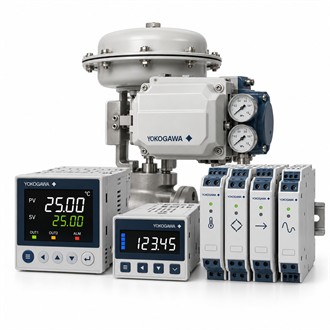
Process-loop and panel-fit review for Yokogawa UT32A-000-10-00
For a new project or an installed-equipment replacement, Yokogawa UT32A-000-10-00 should be evaluated against the actual application. It is a UTAdvanced digital indicating controller. The specification table below provides an early overview; the following sections explain the practical questions to resolve when selecting UT32A-000-10-00.
Key specifications
| Selection point | Specification / confirmation |
|---|---|
| Representative model | UT32A-000-10-00 |
| Instrument role | Panel-mount digital indicating control |
| Family | UT32A standard controller configuration |
| Selection inputs | Measured input, control output and alarm requirements |
| Installation | Confirm panel opening, supply and terminal wiring |
Start with the process loop
UT32A-000-10-00 provides local indication and configured control for a compatible process loop. Selection should connect the measured input, setpoint requirements and final control element. For UT32A-000-10-00, identify the required control action and output format before comparing features; a controller with the same front-panel appearance may have a different input/output or communication configuration.
Panel replacement requires a wiring review
Before replacing an existing unit with UT32A-000-10-00, compare the panel opening, supply, terminals and external connections against the actual instrument code. Preserve the parameter record and document any required changes. For UT32A-000-10-00, verify alarm behavior and the role of retransmission or auxiliary signals rather than transferring settings solely because the displayed process value appears correct.
- Measured signal and control-output format
- Panel dimensions, supply and terminal schedule
- Alarm behavior and required communications
- Parameter backup and loop acceptance criteria
Keep the commissioned settings traceable
Commissioning of UT32A-000-10-00 should verify input scaling, indicated value, control action and the configured response to sensor faults. Adjust control parameters using the approved process procedure and retain a backup of the as-left setup. The record for UT32A-000-10-00 should identify the equipment tag, input sensor and output destination so later maintenance can restore the intended loop configuration.
Interfaces to confirm before ordering
Provide the input and output requirements, power supply, mounting arrangement and the connected equipment details. Include an existing parameter or configuration record when replacing an installed unit. Confirm which accessories and connection hardware belong in the supply. Commissioning should establish the intended signal direction, scaling and response, with the resulting settings retained against the equipment tag for subsequent maintenance and spare-part identification. Preserve the exact UT32A-000-10-00 designation on the enquiry and confirm the offered UT32A-000-10-00 configuration before release.
Ordering and delivery details
For a quotation on UT32A-000-10-00, state the quantity, required delivery schedule and whether the supply is for a new installation or an installed-equipment replacement. Include a legible nameplate where available and identify the documents required with the shipment. Confirm the offered UT32A-000-10-00 code, included accessories and configuration details in writing before release so the delivered package can be checked against an agreed scope.
Related model configurations
- UT32A-D00-10-00
- UT32A-D10-11-00/DC
