


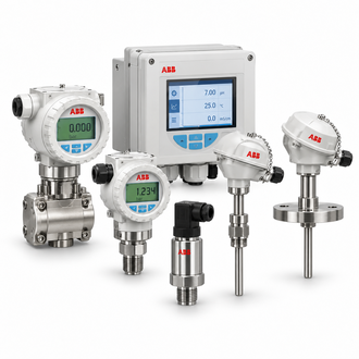
AWT210 transmitter: sensor module, communication choice and process setup
ABB AWT210 is a modular two-wire transmitter for single-channel pH, ORP or conductivity measurement. Its plug-in sensor and communication modules support configuration changes while keeping a common transmitter platform. ABB lists 4–20 mA/HART, PROFIBUS PA and FOUNDATION Fieldbus options, but the string supplied here does not, by itself, prove which modules are fitted. Match the transmitter label and module part numbers before ordering.
Key technical data
| Technical item | Verified value / selection note |
|---|---|
| Complete designation | AWT210.A.1.C2.H1.E5.A1 |
| Family | ABB AWT210 two-wire modular analytical transmitter |
| Measurement platform | Single-channel pH, ORP or conductivity; verify installed sensor module |
| Communication choices | 4–20 mA with HART, PROFIBUS PA or FOUNDATION Fieldbus family options |
| Enclosure protection | IP66 / NEMA 4X family data |
| Mounting | Wall, pipe or panel options, depending on configuration |
| Sensor compatibility | Check electrode, conductivity cell or EZLink module type |
| Exact housing/protocol code | Decode from ABB order record; do not infer from abbreviated string alone |
The values above are intended to identify the listed version and support an initial technical review. Confirm applicable standards, rating conditions, installed accessories and the current ABB documentation for the serial number or revision before design approval, replacement or commissioning.
Application and engineering focus
Choose the measurement parameter and sensor first. pH/ORP electrodes, two- or four-electrode conductivity sensors, toroidal cells and digital EZLink sensors have distinct interfaces, calibration methods and process limits. Confirm temperature compensation, sensor cable, sample point and chemistry. For conductivity-to-concentration applications, validate the selected curve against the process liquid and do not assume the default curve matches a changing mixture.
Configuration, compatibility and related references
Confirm hazardous-area approval, enclosure material, cable glands, output protocol and sensor module configuration for the installation zone. Check loop power and host-system compatibility for the selected two-wire output. Related AWT variants can differ in channel count, wiring architecture or communication options. Keep the order code, module labels, sensor model and calibration records together for maintenance and spare planning.
The related designations below are comparison references, not automatic substitutes. Confirm the complete type code, order number, interface, ratings and revision against the approved application before selecting an alternative.
- AWT210.A.1.C2.H1.Y0-A2.U1.M5
- AWT210.A.1.P1.C2.E5-A2
- AWT210.A.1.P1.H1.E5-A1.U3
- AWT210.A.1.P1.H1.E5-A2
- AWT210.A.1.P1.H1.Y0-A2.U3
- AWT210.A.1.P1.H1.Y0.A1
- AWT210.A.2.C4.H1.E6.A1.U1.M5
- AWT210.A.2.P1.H1.E6-A1.U3
- AWT210.A.2.P1.H1.E6.A1.U1.M5
- AWT210.A1.P1.H1.Y0-A1.U1.M5
- AWT210/A1C2F1Y0A2
- AWT210/A1P1H1E5-A4U1
- AWT210/A1P1H1E6-A4U1
- AWT210/A1P1H1Y0A1U2M5
Installation and commissioning checks
Mount the IP66/NEMA 4X housing where the display is readable and sensor cabling can be routed without excessive noise or mechanical strain. Verify grounding and shielding per ABB instructions. Commission by checking sensor recognition, buffer or reference solutions, temperature input, range and output scaling. Use the appropriate calibration sequence for the sensor type and confirm that diagnostics and alarm status reach the control system.
During commissioning, verify the nameplate, configuration, wiring and diagnostics before enabling normal operation. Test the relevant signal path or protection response end to end under controlled conditions. Record settings and as-left measurements, and investigate abnormal values at the sensor, load, wiring or system configuration before replacing components.
Ordering, replacement and application information
For a quotation or replacement review, provide the complete designation AWT210.A.1.C2.H1.E5.A1, ABB order code where available, serial or hardware revision, quantity, installation environment, connected equipment, interface requirements and target delivery date. Include a clear rating-label photograph and relevant wiring, loop or panel drawing when possible.
Ask the supplier to confirm the exact configuration, accessories, revision and any approved successor in writing. Do not select solely from a family name or product photograph. For safety, grid-protection, medium-voltage or regulated applications, obtain review by the responsible qualified engineer and follow local codes and the manufacturer’s instructions.
