


Application and technical record for NSB10-30GM50-2E2-V1-S2D2
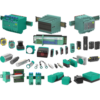
Pepperl+Fuchs NSB10-30GM50-2E2-V1-S2D2 is a safety inductive sensor used to monitor a metal target in a validated safety function. This service brief separates the confirmed identity of NSB10-30GM50-2E2-V1-S2D2 from the installation choices that must be checked on site. The shared Pepperl+Fuchs main image is an illustrative category montage, not an exact photograph of NSB10-30GM50-2E2-V1-S2D2. Use the complete designation on the fitted label when enquiring or replacing the part.
Technical parameters at a glance
| Technical item | Verified value / selection note |
|---|---|
| Exact model | NSB10-30GM50-2E2-V1-S2D2 |
| Product role | safety inductive sensor |
| Rated distance | 10 mm, flush |
| Safety outputs | 2 OSSD |
| Supply | 18 to 30 V DC |
| Connection | M12 V1; check the approved circuit |
| Variant check | Confirm the complete designation and current manufacturer documentation before replacement. |
Replacement file
Before ordering NSB10-30GM50-2E2-V1-S2D2, photograph the nameplate and document what is connected on each side of the device. Check supply, signal or mechanical interface, mounting, environmental exposure and the receiving controller. The table is a compact technical reference for NSB10-30GM50-2E2-V1-S2D2; a similar printed string can denote another function, rating or certification. Retain any parameter backup and the current drawing with the maintenance record.
Functional path
In operation, NSB10-30GM50-2E2-V1-S2D2 is intended to monitor a metal target in a validated safety function. Establish the real input condition, the expected output response and the acceptance limit. Where an accessory, receiver, host card, reflector or magnet is required, include that matched part in the bill of materials. Do not infer that the picture or a neighbouring model code establishes compatibility for NSB10-30GM50-2E2-V1-S2D2.
Wiring and fit gate
At installation, Validate both OSSD channels and the safety controller's test-pulse behaviour. Confirm power is isolated where required and compare the connector or terminals against the current manufacturer documentation for NSB10-30GM50-2E2-V1-S2D2. Verify safe-area and hazardous-area boundaries where applicable; the exact certificate and site wiring govern the final decision. Leave enough clearance for the fitted cable and normal service access.
Proof of operation
Commission NSB10-30GM50-2E2-V1-S2D2 with an observable, known condition rather than only checking an indicator lamp. Record at least two input states and their controller responses, then test the edge of the real working range where practical. If NSB10-30GM50-2E2-V1-S2D2 is part of a safety or Ex installation, use the site's approved proof-test procedure and exact approval documents. Save settings, photos and measured results so a later replacement can be compared reliably.
Buying note
A useful quotation request for NSB10-30GM50-2E2-V1-S2D2 includes the full code, quantity, site function, connection type, any mating accessory and required approval. Ask the supplier to confirm every changed suffix on a proposed alternative. This page does not declare that other visually similar codes are interchangeable with NSB10-30GM50-2E2-V1-S2D2; each requires its own data and fit review.
Visually related codes
The following model strings resemble NSB10-30GM50-2E2-V1-S2D2 in print. They are collected for search and stock recognition only; electrical and mechanical functions can differ. Verify every complete designation independently.
No additional same-pattern designation is grouped with NSB10-30GM50-2E2-V1-S2D2 in this selection.
Handover note
Keep the final NSB10-30GM50-2E2-V1-S2D2 nameplate photo, fit check and test record with the machine file. Re-check the exact model whenever the host, process or installation environment changes.
