


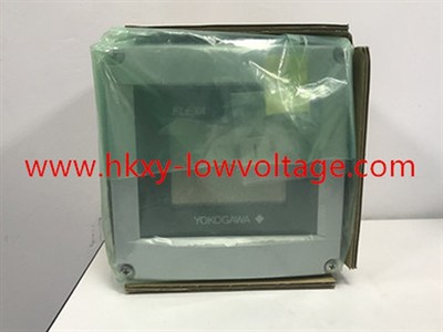
Yokogawa FLXA21 pH and ORP Analyzer with HART and Universal Mounting Hardware
The Yokogawa FLXA21-D-P-D-AA-P1-NN-A-N-LA-N-NN/U is a configured two-wire liquid analyzer for pH and ORP measurement. The P1 input code identifies the pH/ORP measurement module, the A output code identifies a 4–20 mA signal with HART communication, and /U specifies pipe and wall mounting hardware. It is intended for buyers who need local touch-screen operation and a conventional analog loop with digital access for commissioning and diagnostics.
Applications include industrial water treatment, neutralization, cooling-water chemistry, wastewater, chemical processing, food and beverage utilities, pulp and paper, and power-plant water systems. The analyzer is only one part of the measuring loop. The electrode, reference system, temperature element, holder, cable, cleaning method, and installation point determine whether the final measurement is stable and representative.
Configuration and replacement review
Similar FLXA21 enclosures can contain different sensor modules and communication options. A replacement should therefore be matched by the complete suffix, not by the family name alone. Confirm the AA approval configuration, P1 input, NN second-input position, A output, language code, mounting hardware, cable entries, and any project-specific documentation. If an installed analyzer is used in a classified area, verify the required approval rather than assuming this order code is interchangeable with an intrinsically safe version.
Yokogawa publishes a family pH input range of -2 to 16 pH and an ORP input range of -1500 to +1500 mV when used with the appropriate sensor and configuration. Several temperature elements are supported. The final operating range should be based on the process and sensor limits instead of the analyzer’s broad input capability.
| Verification point | Information for this product page |
|---|---|
| Requested model | FLXA21-D-P-D-AA-P1-NN-A-N-LA-N-NN/U |
| Measurement | P1 pH/ORP input with no second input module |
| Output | Two-wire 4–20 mA with HART communication |
| Mounting | /U pipe and wall mounting hardware |
| Housing and display | Plastic enclosure with anti-glare touch display |
| Buyer action | Confirm approval, sensor, temperature element, holder, cable entries and complete suffix |
Sensor and process selection
Define the normal pH, cleaning chemicals, temperature, pressure, solids content, conductivity, and required response time before selecting an electrode. Low-conductivity water may need a sensor and flow arrangement designed to minimize junction potential and atmospheric contamination. Coating, abrasive slurry, oils, proteins, or crystallizing salts require suitable materials and a realistic cleaning plan. ORP service also needs the correct metal measuring element for the process chemistry.
Choose a holder that keeps the sensor in representative liquid and allows safe maintenance. Avoid dead legs, trapped air, excessive turbulence, and poorly mixed reagent injection points. For a sample system, maintain stable flow and prevent contamination. For an immersion installation, confirm that the sensor remains wetted through changing level.
Loop and HART commissioning
Check that the loop supply covers the analyzer, receiving resistor, cable drop, and any isolator or surge protector. HART communication requires suitable impedance and a compatible input card, modem, or asset-management system. Configure measurement mode, temperature element, compensation, output range, damping, burnout direction, tag, and diagnostic limits.
Use fresh traceable buffers that bracket the expected operating point. Allow temperature to stabilize, inspect the reference junction, and record slope and asymmetry results. After calibration, compare the local display, HART value, analog current, and control-system display. Test the failure response before returning the loop to automatic control.
Maintenance planning
Trend calibration results and sensor diagnostics rather than recalibrating by schedule alone. A slow response or increasing asymmetry may indicate coating, aging, poisoning, or reference depletion. Wiring damage, moisture, and incorrect temperature settings can resemble sensor failure. Preserve the final configuration and as-left calibration record so future replacement work can be completed without guessing.
The reused image shows an FLXA-series analyzer but does not provide a readable exact nameplate. Final supply should be verified against the complete model, manufacturer documentation, and order acknowledgment.
