


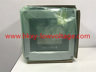
Yokogawa FLXA21 pH and ORP Analyzer with HART for General Process Measurement
The Yokogawa FLXA21-D-P-D-AB-P1-NN-A-N-LA-N-NN is a general-purpose two-wire analyzer configured with a P1 pH/ORP input and a 4–20 mA output with HART communication. It is suited to projects that need local indication, sensor diagnostics, loop-powered transmission, and access to configuration data through a compatible HART host. Common uses include water treatment, chemical dosing, neutralization, food and beverage utilities, pulp and paper, and power-plant water systems.
Successful pH measurement depends on more than the transmitter. The electrode, reference system, temperature element, holder, cleaning method, insertion point, and calibration practice all influence the result. This page therefore treats the listed model as one part of a complete analytical loop and highlights the questions a buyer should answer before replacement or new-project purchase.
What this order code specifies
The P housing code indicates a plastic enclosure and the D display code identifies the anti-glare LCD. AB is the general-purpose CE/RCM configuration in the manufacturer’s suffix table. P1 selects pH/ORP as the first input, NN means no second input, and A identifies the analog/HART output. LA provides the multilingual language set, while the remaining N and NN positions indicate the standard entries shown in the order structure.
Yokogawa lists a pH input range of -2 to 16 pH for the FLXA21 family and an ORP range of -1500 to +1500 mV, with the applicable sensor and settings. Supported temperature inputs include several common RTD and thermistor types. These family values help with initial selection, but the installed electrode and process limits should determine the final operating range.
| Buyer check | Configuration detail |
|---|---|
| Requested model | FLXA21-D-P-D-AB-P1-NN-A-N-LA-N-NN |
| Primary measurement | P1 pH/ORP input; no second sensor module |
| Output protocol | 4–20 mA with bidirectional HART communication |
| Area use | AB general-purpose configuration; not a substitute for an intrinsically safe model |
| Display and housing | Anti-glare touch display in a plastic enclosure |
| Language set | LA multilingual user interface |
Choosing the sensor and holder
Define the normal pH, cleaning chemicals, temperature, pressure, solids content, conductivity, and expected coating before choosing an electrode. Low-conductivity water may need a sensor and flow chamber designed to minimize junction potential and atmospheric contamination. Abrasive slurry, proteins, oils, or crystallizing salts may require a robust junction and a planned cleaning routine. ORP service should be specified separately because the metal measuring element and process chemistry differ from conventional pH measurement.
The holder must place the sensor in representative liquid with adequate flow while allowing safe removal. Avoid dead legs, trapped gas, excessive turbulence, and locations immediately downstream of poorly mixed reagent injection. If the sensor is installed in a retractable assembly, confirm the process valve, insertion depth, pressure rating, and maintenance procedure.
HART integration and control-room use
The analog signal can carry the selected process variable to a PLC or DCS while HART provides configuration and diagnostic access. Confirm the receiving resistance, loop power, cable length, and HART modem or asset-management compatibility. Decide which variable is assigned to the primary output, how failures drive the current, and whether maintenance alerts will be monitored or merely available locally.
A replacement should be compared with the old configuration point by point: range, temperature sensor, compensation method, damping, output scaling, calibration buffers, alarm behavior, tag, and polling address. Saving this information before removing an operating analyzer reduces commissioning time and prevents a mechanically compatible replacement from behaving differently.
Calibration and lifecycle practice
Use fresh, traceable buffers that bracket the normal process value, and allow the sensor and buffer to reach a stable temperature. Rinse without wiping the glass bulb aggressively, inspect the reference junction, and reject calibration when slope or asymmetry falls outside the plant’s acceptance criteria. The analyzer can support diagnostic review, but diagnostics cannot correct a dried, poisoned, cracked, or chemically incompatible electrode.
After installation, compare local indication, HART value, analog current, and control-system display. Test the failure direction and document the as-left calibration. The reused photograph shows the FLXA family rather than a readable exact nameplate, so the complete code, packaging label, and project documents must be verified before shipment.
