


Pepperl+Fuchs NBB25-FPS-A2 Inductive Proximity Sensor
The Pepperl+Fuchs NBB25-FPS-A2 is a rectangular inductive proximity sensor for non-contact detection of metal targets in industrial machinery. Its 25 mm rated operating distance and flush-mounting design make it useful where a compact flat housing is preferred over a cylindrical sensor. Typical duties include position confirmation, conveyor monitoring, machine guarding, end-of-travel detection, fixture presence, and material-handling automation.
Manufacturer data lists a PNP complementary output, 10–30 VDC operating voltage, operating current up to 200 mA, and switching frequency up to 70 Hz. The sensor includes reverse-polarity, short-circuit, overload, wire-breakage, inductive-overvoltage, and surge protection. Green and yellow LEDs indicate operating voltage and switching state for faster commissioning and troubleshooting.
Practical Product Features
- Rated sensing distance of 25 mm for ferrous metal target detection.
- Flush installation in a rectangular FPS-series housing.
- PNP complementary switching outputs for common DC automation circuits.
- Screw-terminal connection compartment for field wiring and replacement.
- IP65 enclosure protection for industrial machine environments.
- Wide published ambient range of −25 to +85 °C for suitable applications.
Application and Mounting Guidance
Sensor performance depends on target material, target size, mounting, temperature, and surrounding metal. The rated distance is a catalog value under defined test conditions; the assured operating distance should be used when setting the machine target. Confirm that the flush-mounting arrangement, approach direction, target geometry, switching frequency, and mechanical clearances suit the application.
Electrical checks should cover the 10–30 VDC supply, PNP input compatibility, normally open and normally closed output use, maximum load current, voltage drop, leakage current, and cable or terminal routing. Protect the sensing face from impact and avoid routing sensor wiring beside high-energy switching or motor cables where electrical noise may affect reliable operation.
Target Design and Machine Integration
Inductive sensing distance is influenced by the target material and dimensions. Standard catalog values are normally based on a defined steel target; stainless steel, aluminum, brass, or a smaller target can reduce the usable distance. The machine designer should provide a target large enough for stable detection and position it within the assured operating range, leaving allowance for vibration, bearing play, thermal movement, and manufacturing tolerances. The target should approach in the intended direction without striking or scraping the sensing face.
Complementary PNP outputs can provide both normally open and normally closed switching states, but the PLC program and wiring must use the correct terminal. During design review, confirm whether the input card expects sourcing signals, how common conductors are arranged, and what state represents a safe or normal machine condition. If the sensor monitors a guard, travel limit, or critical position, the overall safety function must be evaluated separately; a standard proximity sensor is not automatically a safety-rated protective device.
Commissioning and Troubleshooting
Set the target position while observing the switching indicator, then verify repeatability through multiple machine cycles. Test at the lowest and highest expected temperatures if the application has significant thermal variation. Check for false switching when adjacent metal parts move, when nearby solenoids or motors operate, and when the supply voltage is at its allowable limits. The final mounting and target position should provide a comfortable operating margin rather than switching at the extreme edge of the sensing range.
If the sensor does not switch, confirm supply polarity, voltage at the terminals, output wiring, PLC common, target material, and target distance before replacing the device. Intermittent operation may indicate a loose terminal, damaged sensing face, moving bracket, electrical noise, overload, or insufficient target overlap. Record the model, wiring, measured gap, and LED states during troubleshooting. A correctly documented spare can then be installed with less risk of changing the original switching logic or mechanical alignment.
Photo and Receiving Verification
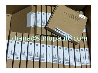
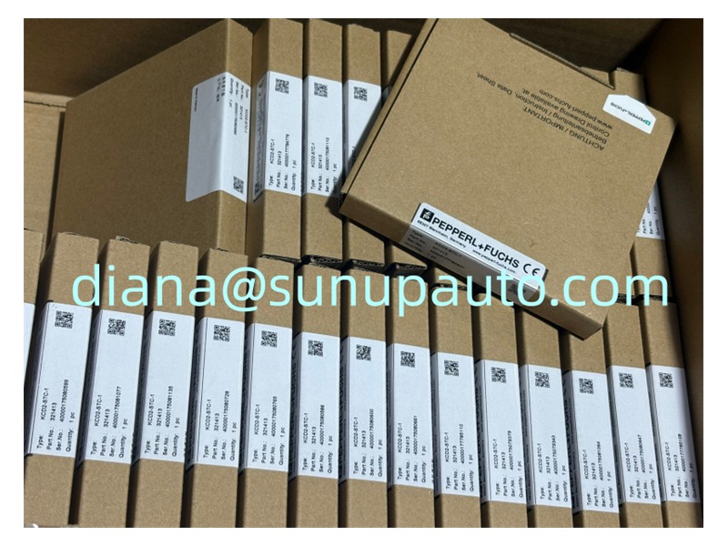
The supplied photograph shows Pepperl+Fuchs inventory cartons, and the visible labels appear to include KCD2-series interface modules rather than a clearly identifiable NBB25-FPS-A2 sensor. It is therefore used as a brand reference only. Receiving inspection must confirm model NBB25-FPS-A2, 25 mm sensing distance, PNP complementary output, terminal housing, supply rating, production label, and package condition.
For pricing and delivery, provide the requested quantity, target material and size, mounting arrangement, PLC input type, required certificates, destination, and delivery date. If replacing an installed sensor, include photos of the existing label, wiring terminals, mounting space, and target so that the requested model and switching behavior can be verified before supply.
