


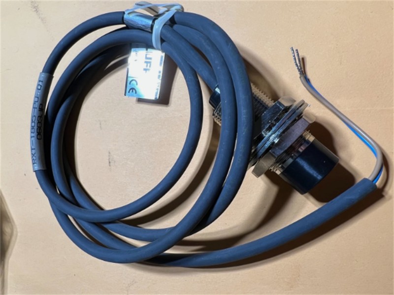
Balluff RST-1805-PU-1 Contactless Remote Sensor Transmitter
The Balluff RST-1805-PU-1 is associated with a legacy inductive remote-sensor system designed to transmit a switching signal across a short air gap without exposed electrical contacts. RST-type transmitters are used with an appropriate mechanical limit switch and a matching remote output sensor. This arrangement can remove a plug-and-socket connection from a moving interface and reduce wear in machines where fixtures, pallets, tools, or rotating assemblies are exchanged frequently.
The RST-1805 family uses an M18-format transmitting head. Legacy remote-system documentation describes the RST-1805-PU as a one-signal transmitter for a mechanical limit switch, paired with an RXE-1805 output sensor. The exact suffix, cable length, connector, transmission distance, and output-side PNP or NPN choice depend on the complete system. RST-1805-PU-1 should therefore be checked against the installed mating receiver and the original machine drawing before purchase.
Where Contactless Signal Transfer Helps
Remote sensor systems are useful on assembly pallets, rotary index tables, robot tooling, welding fixtures, packaging equipment, and transfer lines. A mechanical limit switch can remain on the moving section while the output sensor stays connected to the stationary control system. When the two inductive faces align within the permitted distance, power and switching information pass across the interface. The arrangement can simplify tool changes and avoid connector pins that would otherwise be exposed to coolant, dirt, vibration, or repeated handling.
The machine designer should define the safe state if the inductive link is lost. A missing fixture, excessive gap, damaged cable, misaligned head, or failed mechanical switch can all produce an inactive control signal. The PLC program and machine diagnostics should distinguish a normal open-switch condition from a communication or alignment problem where possible. This is especially important when the signal is used for position confirmation or cycle permission.
Key Product Data
| Verification point | Information for this product page |
|---|---|
| Requested model | RST-1805-PU-1 |
| System function | Contactless transfer of one mechanical-switch signal |
| Transmitter format | M18 cylindrical remote-system head |
| Typical mating device | RXE-1805 family output sensor; exact PNP/NPN version must match the controller |
| Published family distance | Approximately 4 to 5 mm, depending on the specific legacy variant and mounting |
| Verification required | Full suffix, cable, mating receiver, output logic, gap, alignment, and machine interface |
Mechanical Installation and Alignment
Install the transmitter and output sensor so their active faces remain parallel and centered throughout the complete machine movement. Maintain the specified face-to-face distance and observe the required clearance from surrounding metal. Bracket deflection, bearing play, vibration, and thermal growth can change the effective gap even when the system is correctly aligned during maintenance. The installation should provide enough operating margin for normal mechanical variation.
Support the cable close to the device without applying tension to the sensor body. Protect the cable from sharp edges, weld spatter, repeated flexing, and contact with moving components. Keep low-level control wiring away from motor and high-current switching cables to reduce inductive interference. If the machine uses several remote pairs close together, follow the manufacturer’s minimum spacing guidance to prevent mutual interference.
Electrical Integration and Commissioning
Confirm the mechanical switch wiring, supply arrangement, mating RXE model, output logic, controller input common, and switching frequency before energizing the system. PNP and NPN output receivers are not interchangeable without changes to the PLC input circuit. Check that the selected output sensor can drive the intended input load and that the power supply is regulated within the required limits.
Commissioning should test the switch state, link state, and PLC indication separately. Operate the machine through the full cycle at normal speed, then repeat the test at the maximum expected offset and vibration. Record the final gap, bracket position, cable routing, and LED indications. A documented known-good transmitter and receiver pair can shorten future troubleshooting.
Photo and Part-Number Notice
The reused photograph shows a cylindrical remote-system component marked RXT-1805-PU-01. RXT and RST transmitters serve different detector arrangements, so the image is a related family reference rather than proof of RST-1805-PU-1. Final identification must use the product label, wiring diagram, complete suffix, mating RXE output sensor, and the installed mechanical-switch circuit.
For quotation and compatibility review, provide the requested quantity, photos of both existing remote heads, cable details, mechanical switch type, controller input logic, operating gap, mounting dimensions, and delivery destination. These details help prevent an RXT detector transmitter or an incorrect PNP/NPN receiver from being supplied for an RST mechanical-switch application.
