


AF09-30-01-13 three-pole contactor: ratings, coil range and ordering checks
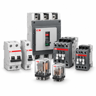
ABB AF09-30-01-13 is a three-pole AF-series contactor. The summary below identifies the principal ratings for order code 1SBL137001R1301; final selection must still be checked against the motor nameplate, utilization category, operating duty and local installation rules. The category image is illustrative and does not depict this exact coil or terminal configuration.
Key technical data
| Technical item | Verified value / selection note |
|---|---|
| ABB order code | 1SBL137001R1301 |
| Type designation | AF09-30-01-13 |
| Main poles | 3-pole |
| Rated operational power | 4 kW at 400 V AC-3 |
| Rated operational current | 9 A AC-3; 25 A AC-1 under stated reference conditions |
| Built-in auxiliary contact | 1 NC |
| Control coil | 100–250 V AC, 50/60 Hz, and 100–250 V DC for the -13 coil variant |
| Family | ABB AF motor contactor |
The values are selection data, not a replacement for the current ABB datasheet or engineering review. Ambient temperature, enclosure, switching frequency, motor starting current and coordination with upstream protection influence the complete starter design. Check the product label and current regional documentation before design release.
Motor duty and sizing
Begin with the motor rated current and actual switching duty rather than selecting by frame size alone. AC-3 is the usual utilization category for starting a squirrel-cage motor and switching it off while running. Inching, plugging, rapid reversal, frequent starts or high inertia can impose a more demanding duty. Compare the contactor rating at the actual operating voltage with motor full-load current and expected starts per hour.
Select short-circuit protection and overload protection as a coordinated starter combination. A contactor is not itself an overload relay or short-circuit protective device. Coordination depends on prospective fault current, upstream protective equipment and the applicable standard. For drive or soft-starter installations, confirm whether the contactor is intended for isolation, bypass or line switching and follow the equipment manufacturer’s switching guidance.
Auxiliary contact and coil
The 01 suffix identifies one normally closed auxiliary contact. Confirm that the control schematic expects an NC feedback or interlock path; a nearby AF09 designation can have a different auxiliary arrangement. Verify the intended energized and de-energized logic states, especially when the auxiliary contact feeds a PLC or safety-related interlock.
The -13 coil variant is rated for a broad 100–250 V AC/DC operating range. Check both the control supply’s nominal voltage and whether it is AC or DC, including tolerance and transients. Main-circuit voltage does not establish coil suitability. Preserve the complete suffix when replacing a device even if its housing looks identical.
Related AF09 designations
The related AF09 codes below are identification references, not automatic substitutes. Coil suffix, auxiliary contacts and contact arrangement can differ. Compare the full code, control supply, wiring diagram and installed accessories before considering an alternative.
- 1SBL137001R1310, AF09-30-10-13
- 1SBL137201R1300 AF09-40-00-13
- 1SBL137201R1300(AF09-40-00-13)
- AF09-30-01-11
- AF09-30-10-11
- AF09-30-10-11 24-60V50/60HZ 20-60VDC
- AF09-30-10-13
- AF09-30-10-13 (1SBL137001R1310)
- AF09-30-10-13 1SBL137001R1310
- AF09-40-00-13*100-250V AC/DC
Installation and wiring checks
Isolate the power circuit and control supply before installation. Check the nameplate against the approved schematic, mounting orientation, enclosure clearance, conductor cross-section, terminal preparation, tightening torque and heat dissipation against ABB instructions. Verify line, load, coil and auxiliary terminals individually; keep control and power wiring routed as required by the panel design.
For reversing or changeover arrangements, use engineered electrical and/or mechanical interlocking where required. Check that the feedback contact is the intended NC contact and is wired to the correct logic input. Before energizing, inspect for loose strands, contamination, shipping damage and unintended continuity across the power poles.
Replacement and quotation checklist
Provide exact designation 1SBL137001R1301 AF09-30-01-13 and order code 1SBL137001R1301, quantity, control-coil supply type and voltage, motor rating/current, system voltage, utilization category, auxiliary-contact requirement, mounting/accessories and destination. A clear label photo and terminal-wiring photo help resolve suffix differences before dispatch.
Ask the supplier to confirm the exact variant, product revision, documentation and accessories. If a nearby AF09 code is proposed, request written confirmation against the actual circuit and duty rather than relying on appearance. Keep the selected part and protection-coordination details in the maintenance record.
