


Confirming the installed interface for FS-LB-I
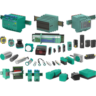
Pepperl+Fuchs FS-LB-I is a intrinsic-safety surge protection barrier used to protect an instrument signal circuit from surge energy. This entry identifies the complete FS-LB-I designation and shows the technical data that can be used as a starting point. The shared main image is a Pepperl+Fuchs category reference montage, not an exact photograph of FS-LB-I. Final selection still requires the fitted label, the latest manufacturer record and the actual site drawing.
Key technical data
| Technical item | Verified value / selection note |
|---|---|
| Exact model | FS-LB-I |
| Product role | intrinsic-safety surge protection barrier |
| Protection | Surge barrier for instrument line |
| Mounting | M20 x 1.5 thread |
| Housing | Stainless steel, IP67 |
| Approval | Verify Ex ia certificate for the installed circuit |
| Variant check | Confirm the complete designation and current manufacturer documentation before replacement. |
System boundary
The job of FS-LB-I is to protect an instrument signal circuit from surge energy. Define its boundary in the real installation: what connects upstream, what response is required downstream, how it is powered and how it is mounted. A model that looks like FS-LB-I may not provide the same circuitry or approvals. Capture the present configuration before removal, including any addresses, calibration, scaling, taught limits or software settings.
Replacement gate
For a replacement FS-LB-I, compare the full printed code character by character. Confirm supply, I/O direction, signal type, terminal or plug pinout, operating environment and mechanical clearances. If the circuit has functional-safety or hazardous-area requirements, obtain the exact approval documents for FS-LB-I; the visual similarity of another code is not a valid substitute. Include mating heads, reflectors, boards, cables and licences as separate line items where needed.
Record the complete FS-LB-I code before comparing any similar-looking part.
Acceptance evidence
At commissioning, Check M20 fit, earthing and the exact Ex circuit limits. Test FS-LB-I in the assembled system using a known input or mechanical condition, then read the corresponding output and controller response. Repeat at the low and high ends of the real operating window. A status LED alone cannot prove that FS-LB-I has the correct settings, connected accessory or alarm action. Keep the measured values and any deviations in the maintenance record.
Purchasing handoff
An RFQ for FS-LB-I should quote the complete designation, required quantity, installed controller or host, connection style, certification need and the intended operating environment. Request confirmation for any alternate suffix. Related-looking models are indexed below to help identify inventory, but technical table values on this page apply only to the named FS-LB-I variant where verified. Each other complete code needs its own specification review.
Related-looking model strings
These designations visually resemble FS-LB-I; they can still have different functions, ratings, interfaces and approvals. Verify each complete code independently before ordering or substitution.
No additional same-pattern code is grouped with FS-LB-I here; any alternative requires its own review.
Close-out
After the handover of FS-LB-I, archive the exact label, configuration backup, drawings and test result. If the process or host changes later, redo the relevant match and acceptance checks for FS-LB-I. Do not treat the product montage or the related-code index as a wiring diagram or a declaration of interchangeability.
