


Checking PGV100-F200A-R4-V19 against the installed equipment and the required signal path
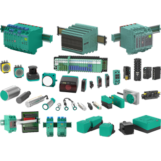
Pepperl+Fuchs PGV100-F200A-R4-V19 is a optical positioning read head used for reading coded position and lane guidance without contact. This page identifies the representative designation and the checks that matter when the device is selected for a real installation. The common product montage is a category reference image, not a photograph of the exact PGV100-F200A-R4-V19 unit. Compare the full label and current manufacturer data before committing a purchase or changing a live circuit.
Key technical data
| Technical item | Verified value / selection note |
|---|---|
| Exact designation | PGV100-F200A-R4-V19 |
| Product type | optical positioning read head |
| Communication | RS-485 |
| Read distance | 100 mm nominal |
| Position reference | Data Matrix code tape or tags |
| Light | Integrated white/blue illumination |
| Variant boundary | Use the complete type code and current device label when selecting a replacement. |
Operating role and application
In the intended system, PGV100-F200A-R4-V19 is used for reading coded position and lane guidance without contact. Its role is not defined by the product picture or a shared prefix alone. Establish what arrives at the device, what leaves it and which controller, field instrument or mechanical component it must match. When PGV100-F200A-R4-V19 is ordered as a spare, preserve the complete suffix and all installed configuration information.
Commissioning and maintenance
After fitting PGV100-F200A-R4-V19, Run the vehicle or mechanism through the route and check position, lane transitions and loss-of-code behavior. Record both the expected and observed behavior. Inspect indicators, fault response and controller diagnostics where provided. If the test does not match, verify wiring, configuration and connected equipment before assuming that a new PGV100-F200A-R4-V19 is defective.
Interface and installation fit
For PGV100-F200A-R4-V19, Verify code-tape type, 100 mm standoff, optical alignment, connector and RS-485 parameters. Review the mating equipment, supply path, mounting space, cable or terminal assignment and any required hazardous-area documentation. If the present installation has field-modified wiring or programming, photograph and record it before removal. The same-looking item can require different wiring or settings.
Procurement and replacement details
When requesting PGV100-F200A-R4-V19, Quote the entire PGV100-F200A-R4-V19 designation with tape or tag type and interface settings. State operating environment, required certificates and the exact application. Request written confirmation for any proposed alternative. A reference model in the list below may belong to the same visible naming cluster but is not a default functional replacement for PGV100-F200A-R4-V19.
Related designation references
The following catalog designations share the visible PGV naming cluster with PGV100-F200A-R4-V19. They are grouped to aid search and procurement, not to assert identical ratings, wiring, approvals or interchangeability. Each complete code must be checked separately against the required duty.
For PGV100-F200A-R4-V19, confirm any proposed variant against the complete manufacturer designation, electrical data and mechanical fit before placing an order.
Final selection check
For PGV100-F200A-R4-V19, confirm the latest datasheet and nameplate before ordering or commissioning. Retain the loop drawing, configuration and acceptance record with the maintenance file. The technical values above apply to PGV100-F200A-R4-V19 only where stated, not to every related designation.
